
PRODUCTS
LATEST MEWS

Company: Shenzhen Rev Laser Equipment Co., Ltd
Website: www.revlaser.com. cn
Address: 2nd Floor, Building A, Tongfuhan Haida Innovation Park, No. 10 Jiangfu Road, Matian Street, Guangming District, Shenzhen
Mobile: +86-15889513597
Email: revlaser@163.com
Laser Repair Machines
HomeLaser Repair MachinesDetails
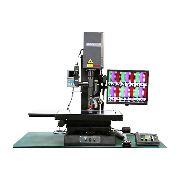
Semiconductor Laser Repair Machine REV-323-ZW
Equipment introduction:
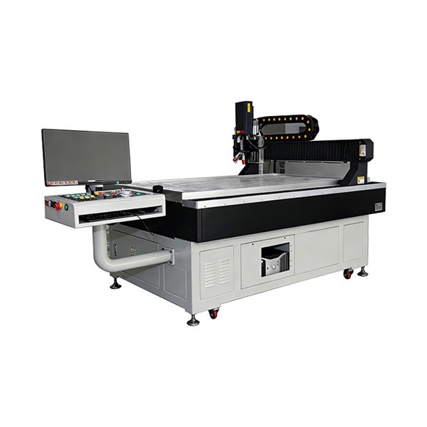
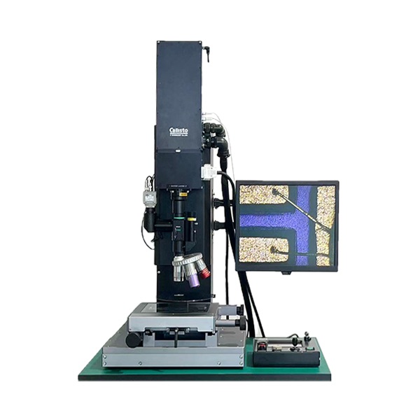
Semiconductor laser repair machine is a precision processing and repair equipment specially developed for semiconductors, microelectronics and other fields. The core is used for high-precision laser repair operations.
The equipment is equipped with a special laser (laser) system, a precision optical imaging system (including a special microscope for laser processing/observation, a special optical objective for laser processing, and an image observation objective), an X/Y/Z three-axis manual displacement and focusing system, supplemented by a precision marble platform base and a simple open work carrier form a highly stable processing system. The equipment is deeply adapted to the entire process needs of the semiconductor industry chain and can be widely used in laboratory analysis, packaging and manufacturing, R & D debugging, and process defect repair. It can accurately strip and repair defects on specific material layers of workpieces, effectively reducing product scrapping rate, significantly reducing production costs.
Basic information
product model | REV-323-ZW | working environment | open |
power demand | 220V,50~60Hz | control methods | manually |
Product size | 800mm x 550mm x 1600mm | equipment weight | Approximately 120KG |
Technical characteristics and advantages
● High-end core configuration is supported, leading the industry in repair stability ● Multi-dimensional and precise control to adapt to complex repair scenarios ● Comprehensive optical imaging system for more accurate defect identification and repair ● Strong flexible adaptation capabilities ● Software functions are more suitable for industrial-level operation needs ● The balance of customization and compatibility is more advantageous
Application field
Precision machining and repair in the fields of semiconductors and microelectronics (core applications of laser micromachining systems)
Polyimide (PI) semiconductor packaging layer peeling
Core advantages: 3-5μm thick encapsulation layer is stripped, the efficiency is 3-5 times that of FIB, and there is no ion pollution
Application scenarios:
Failure Analysis Laboratory: Fault Location within the Chip
Power chip packaging rework: repair of defective IGBT modules
Advanced packaging R & D: 2.5D/3D packaging PI layer trimming
Surface removal of silicon dioxide (SiO₂) circuit metal lines
Core advantage: Remove the SiO₂ layer on the surface of the metal line without damaging the metal line below
Application scenarios:
Semiconductor device production line: CMOS chip insulation repair
MEMS sensor development: pressure sensor film adjustment
RF chip manufacturing: GaN chip passivation layer treatment
Metal circuit (gold/aluminum) wire cutting and capacitor trimming
Core advantages: Circuit line cutting and capacitor size trimming to avoid damage to silicon/gallium arsenide substrate
Application scenarios:
Failure analysis and verification: chip short circuit fault confirmation
RF chip debugging: power amplifier chip parameter matching
Wafer test post-processing: Poor isolation of logic chips
Core equipment for reducing costs (rework), improving yields (repair), and accelerating R & D (debugging) in the semiconductor industry
1. Machine specifications
| X/Y/Z axis drive system | |
| project | description |
| Effective travel in X, Y, and Z axes | 130mm x 130mm x200mm |
| X and Y axis drive form | 1um/pulse (manual adjustment of displacement) |
| reproducibility | 100mm |
| Z-axis drive form | Precision screw (electric adjustment displacement focus) |
| Z-axis minimum resolution | 0.1um/pulse |
| (Subject to the actual design configuration) | |
2. Laser system
2-1 You can choose New Wave, REV-3018 and other series laser systems, according to the cutting material configuration requirements.
(Subject to the actual laser configuration).
| 2-2 Laser Slit | |
| project | description |
Repair size | Lens magnification processing size |
| NIR 50x objective; min: 3um x 3 um | |
| NIR 20x objective lens max: 120um x 120um | |
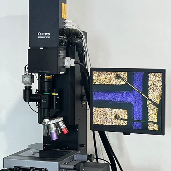
| 2-3 optical image system | |
| project | description |
| microscope | Observation/laser processing special type |
| CCD | 1/2”Color CCD |
| epi-light source | High-brightness LED point light source |
| transmission light source | backlight |
| Guide Light | LED(Blue) |
| objective lens switching system | 4 holes/manual switching type |
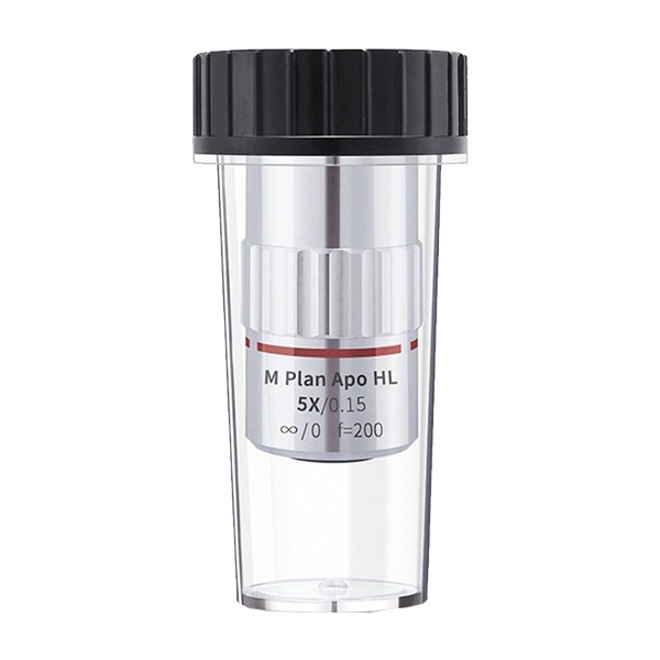
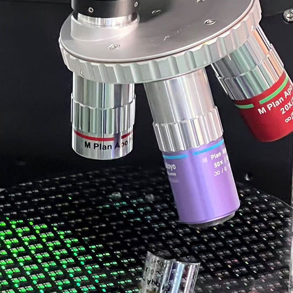
| 2-4 Precision objective lens group | |
| project | description |
| M Plan APO 5 x | observation |
| M Plan APO 10 x | observation |
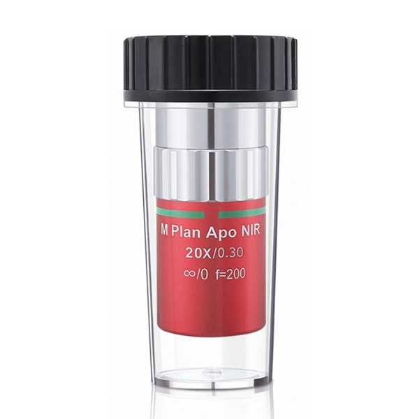
| M Plan NIR 20 x | Observation/laser processing |
| M Plan NIR 50 x | Observation/laser processing |
| 2-5 autofocus system | |
| project | description |
| Focus type | Manual focusing |
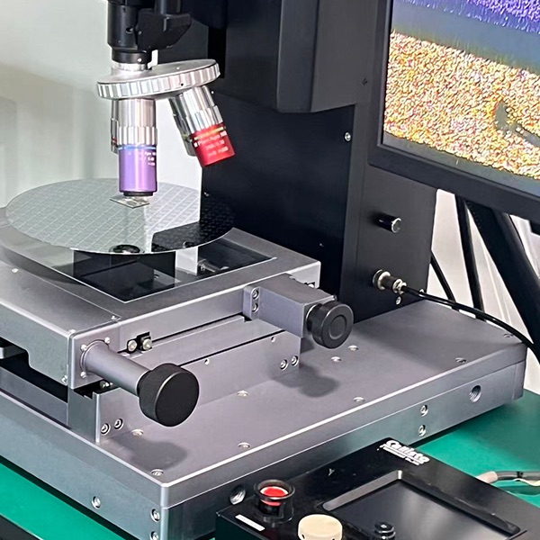
| 2-6 processing stage | |
| project | description |
| main function | Workpiece carrying use |
| material | Precision Grinding Optical Glass Stage |
| size | 200mm x 200mm(customizable) |
| base table | Precision marble |
| 2-7 suspension system | |
| project | description |
| Shock absorber form | Shock absorber form |
| Natural frequency (vertical/horizontal) | 2~2.3 Hz |
| Manufacturer gas supply specifications | 4~6 kg/㎠ (Compressed or Nitrogen Gas) |
| (Equipment requirements floor shockproof level: Level B) | |
| 2-9 other specifications | |
| project | description |
| backlight box | Looking for highlights and defects of light source light box |
3. Operation mode
3-1 Software features no
(1) Laser control box
(2)Laser manual operation firing function (foot pedal).
(3)Manual XYZ three-axis displacement focus, and the screen cursor moves.
(4)The matching settings of standard parameters of the control box are adjustable.
(5)The control box knob turns on the Slit function. The cursor movement on the screen corresponds to the adjustment of Slit size.
(6)User login/login key power switch.
(7)Manual adjustment of upper and lower light sources.
(8)The upper and lower light sources are adjusted manually in conjunction with each magnification setting.
(9)Lens switching manual correction function.
(10)Operate the English menu.
3-2 In manual operation mode, the operator can manually adjust and move XYZ and confirm it through the system screen.
4. Public equipment
| 4-1 power supply | |
| project | description |
| number of groups | 1 group |
| power supply | 2 phase /AC 220 V ± 10%, 30A |
| power connector | M6 terminal block |
| ground line | JIS level 1,8 mmsq or above |
5. appearance
| project | description |
| number of groups | 2 groups |
| size | Within 800mm(W) x 550mm(D) x 1600mm(H) |
| weight | Within 120KG |
| (Based on the actual design size) | |
6. use environment
| temperature | 20℃±5℃ |
| humidity | 30~60 (no dew condensation state) |
| dust | It is recommended for use in clean rooms above level 10000. The laser is a combination of optical parts and therefore is used in an environment with less dust. |